Normally Open Contacts on a Relay Will Read
It is a two-terminal device and which is used in electrical and electronics circuits for controlling the one or more circuit. Test the Relay Contacts with an Ohmmeter.

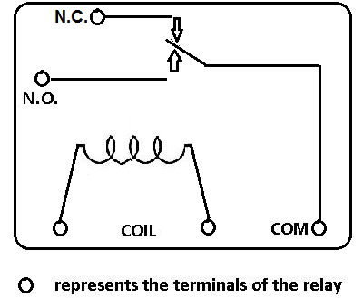
Normally Open Vs Normally Closed Relay Diagrams Symbols
If when a relay coil has 0 volts two contacts make a complete circuit then that contact set has a normally closed configuration.

. Normally-open switch contacts are sometimes referred to in the electrical industry as form-A contacts. If you read a very low resistance and very high resistance the coil is either shorted or is open. Normally open or normally closed.
Contacts closed until activated bContacts open until activated c. Transformer action is based on. You should definitely test this using a multi-meter.
It contains two vertical lines one on the extreme left and the other on the extreme right. The slash mark across the two vertical lines indicates the contact is Normally Closed. At the point when the relay works the common and NO will make a closed circuit and positive supply flows to load.
A small power circuit can handle multiple high current circuits using a relay. It means if you connect it in a circuit by default it wont allow you to pass the current. In a closed state is called normally closed contacts the circuit symbol as shown in the figure below.
Take the multimeter and put it in ohm or continuity mode. These vertical lines are called rails. Rarely are these familiar examples good for learning but a 3 way switch is an excellent example of using normally open and normally closed switches.
How To Check Normally Open NO Relay Contacts Identify the relays high amperage circuit. The lamp will energize only if someone presses the switch holding its normally-open contacts in the closed position. Air between the coils c.
A normally open relay NO will have. To show the location of all the electrical components To show how the power. The middle pin is always connected to the pin on the right NORMALLY CLOSED whenever the relay is turned on this middle pin is connected to the pin on the left NORMALLY OPENED.
Nov 10 2016 at 1951. In case you need a short refresher about relay contacts an example of a Normally Closed contact is shown in the lower left corner of this drawing. Normally open contacts would represent relay contacts that would perform a connection upon receipt of a signal.
Normally open contacts on a relay will read Infinity OL when the relay is de-energized and 0 when energized When is the 0 terminal energized on most low voltage thermostats. There are 2 types of 4 pin relay available. In this case since coils normally are not repaired you must simply replace the relay.
If you read a value about the rated coil resistance the coil works and should function correctly. People who searched normally open contacts on a relay will read also searched. In relay logic circuits the contacts NO and NC are used to indicate Normally Open or Normally Close relay circuit.
4 Pin Relay 4 pin relays use 2 pins 85 86 to control the coil and 2 pins 30 87 which switch power on a single circuit. Unlike open contacts with normally closed contacts signal will interrupt a contact or turn a relay off. Why use a Relay.
The fact that the vertical lines have no slash between them tells you the relay contact is a Normally Open circuit. The following is a timing diagram of this relay contacts operation. BR the relay contactor is open when power is called normally open contacts.
Now lets go through a real-world example of normally open and normally closed contacts that we are all familiar with. Next we have the normally-open timed-open NOTO contact. A normally open set of relay contacts will close when Power is applied to the relay coil Power is not applied to the contacts Power is applied to the contacts Power is not applied to the relay coil.
A positive voltage is associated with the normal pin of the relay and the supply passes through the normally open contacts. Like the NOTC contact this type of contact is normally open when the coil is unpowered de-energized and closed by the application of power to the relay coil. Intermediate relay normally open and normally closed contacts is refers to the state of the intermediate relay is in a state of loss of electricity.
Previous picture shows what this looks like in practice. Touch the multimeter ohm or continuity leads with the relays high amperage circuit If you get some reading in. Mutual inductance NAT ECET e M aECET 4.
A normally open relay will switch power ON for a circuit when the coil is activated. The conditions Normally open NO and Normally closed refer how the contacts sit when the switch is off or the relay coil voltage is 0. NO in relay is nothing but a Normally Open.
If we had used a normally-closed pushbutton switch instead the behavior would be exactly opposite. The purpose of the schematic diagram is. The extreme left rail is at the supply voltage potential and is used as an input rail.
Here Normally open indicate the contact will be in open by default. All contacts permanently closed 2. All contacts permanently open d.
The easiest way to explain them is in the example of a relay.
How To Test The Relay Contacts

Normally Open No Vs Normally Closed Nc

Normally Open Vs Normally Closed Relay Diagrams Symbols


Comments
Post a Comment